- On sale!
PUIG CURVE 9151N REAR INDICATORS
Recibe este producto sin gastos de envío
PUIG CURVE 9151N REAR INDICATORS
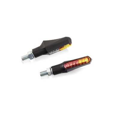
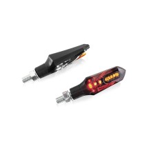
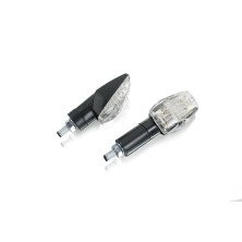
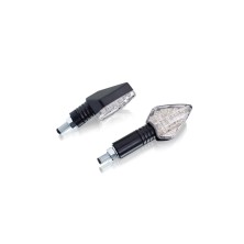
Revolutionize the image of your motorcycle with the Curve indicators from Puig. Set of approved LED indicators with black housing and transparent glass.
Approved
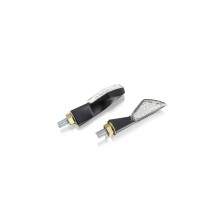
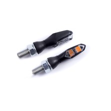
Front set with black transparent glass of 49.50 x 25mm LEDs. (LxW)
M8 thread
POSITION + INDICATOR.
THE INDICATOR IS APPROVED, NOT THE BRAKING OR POSITION SIGNAL
REF.9084 N
Approved
Rear set with black transparent glass of 49.50 x 25mm LEDs. (LxW)
M8 thread
POSITION + STOP + INDICATOR.
APPROVED FLASHING SIGNAL, NOT BRAKING OR POSITION SIGNAL
REF.9151 N
For this product Puig has different flashing variants available:
A reference (9084N) for the front indicators with position and flashing function (49.50x25mm) and another reference (9151N) for the rear indicators with position, stop and flashing function (49.50x25mm).
Technical Information Flashing Connection:
Most motorcycles use bimetallic relays. Their frequency (which is what sets the flashing rhythm) depends on the amperage that circulates through the circuit. When replacing the original flashing lights with others of a different power, we vary the amperage that circulates through the circuit and consequently we vary the flashing frequency of the flashing lights. If, on the other hand, the motorcycle uses electronic relays (whose frequency is independent of the amperage circulating through the circuit), changing the turn signals should not affect the blinking frequency.
· Note: if you are unsure which relay your motorcycle uses, it is advisable to fit the turn signals and check the blinking frequency.
If we replace the original turn signals with others that also use incandescent bulbs, we must check that they have the same wattage. If it varies, we must replace the turn signal bulbs with others of the same wattage as the originals. In our catalogue we have boxes of bulbs of different wattages.
If we replace the original turn signals with LED ones (of a much lower wattage than incandescent bulbs), we have two options to balance the blinking frequency:
1. Incorporate a resistor in parallel in the right-hand side circuit and another in the left-hand side circuit. If we replace all four turn signals, we must use resistor Ref. 4298O. If, on the other hand, we only replace two indicators (one on each side), we must use the resistor Ref. 5873O.
A diagram for connecting them in parallel is supplied with the resistors.
· Note: in most models, the use of resistors prevents the warning from working correctly.
2. Identify the flasher relay on our motorcycle (location and number of pins) and replace it with the corresponding one from the list we offer. In most motorcycles, when changing the relay, the warning works correctly.
· Note: there are some motorcycles on the market that do not have a specific flasher relay, so it is impossible to replace it. Also, if more than one relay is involved in the flashing manoeuvre, it is possible that replacing just one relay will not solve the problem.
· Note 2: some LED flashers flash faster than normal when connected to power (it is normal to check the polarity of the cables with the flashing function activated). To check the actual flashing frequency, remove all power by turning the key to the “off” position and then turn it to the “on” position to activate the flashing function.

