- On sale!

Te quedan 59€ para el envío gratis
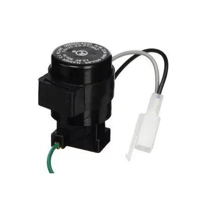
PUIG RELAY 3 OUTPUTS FOR INDICATORS 4822N
If you are looking for a uniform and intense flashing of your indicators, buy Puig Relays.
PUIG RELAY 3 OUTPUTS FOR INDICATORS 4822N
If you are looking for a uniform and intense flashing of your indicators, buy Puig Relays.
Technical information on the connection of indicators:
Most motorcycles use bimetallic relays. Their frequency (which is what sets the rhythm of the indicators) depends on the amperage that circulates through the circuit. When replacing the original indicators with others of different power, we vary the amperage that circulates through the circuit and consequently we vary the frequency of the blinking of the indicators. If, on the other hand, the motorcycle uses electronic relays (whose frequency is independent of the amperage that circulates through the circuit), the change of indicators should not affect the frequency of blinking.
Note: if you are unsure of which relay your motorcycle uses, it is advisable to mount the indicators and check the frequency of blinking.
If we replace the original indicators with others that also use incandescent bulbs, we must check that they have the same power. If the light changes, we must replace the indicator bulbs with others of the same power as the original ones. In our catalogue we have boxes of bulbs of different powers.
If we replace the original indicators with LEDs (of a much lower power than incandescent bulbs), we have two options to balance the blinking frequency:
1. Incorporate a resistor in parallel in the circuit on the right side and another in the circuit on the left side. If we replace all four indicators, we must use the resistor ref.4298O. If, on the other hand, we only replace two indicators (one on each side) we must use the resistor ref.5873O.
A diagram for their parallel connection is supplied with the resistors.
Note: in most models, the use of resistors prevents the "Warning" from working correctly.
2. Identify the flasher relay on our motorcycle (location and number of pins) and replace it with the corresponding one from the list we offer.
On most motorcycles, replacing the relay causes the "Warning" to work correctly
Note: there are some motorcycles on the market that do not have a specific flasher relay, which makes it impossible to replace it. Also, if more than one relay is involved in the flashing manoeuvre, replacing just one relay may not solve the problem.